About a decade ago the European Machinery Directive came into force. This directive requires every machine sold in the European Union to undergo a risk analysis and meet certain safety requirements. A machine that meets these requirements may be marked with the well known CE symbol.
A manufacturer of machines can carry out this safety analysis himself. The analysis is based on a standard list of hazards for which measurements need to be taken. The general list of hazards and risks of any machine is rather vague, so it is much more convenient to follow a standard that specifies requirements for a certain product.
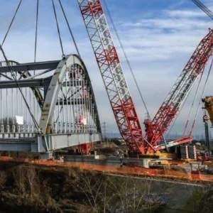
At the moment various committees working on provisional European standards (or prEN), helping to fulfil the Machinery Directive for a number of different crane types. Every standard will have the same format, based on a risk analysis. The offshore cranes standard, prEN 13852, is split into two parts: one for general-purpose cranes and one for floating cranes. Both are still provisional, hence the abbreviation ‘pr’. Although the general purpose section has reached the final draft stage, the floating crane part has not advanced so far.
The standard is prepared by representatives from Norway, the UK, Austria, Germany and the Netherlands, representing crane manufacturers, classification societies, national standardisation institutes and crane owners. Comments on the standards were received from all European countries involved in the offshore crane industry.
prEN 13852 part 1: General Purpose Offshore Cranes covers slewing cranes mounted on an offshore installation whose duties include load handling to and from supply vessels, barges or semi submersibles. For cranes on fixed platforms this standard is mandatory. For floating installations this question depends on the nature of the operations, because machines mounted on sea going ships are excluded from the Machinery Directive. prEN 13852 part 2: Floating Cranes covers cranes mounted on a vessel or barge designed for its support and transport, primarily intended for construction and deconstruction operations in a marine environment. prEN 13852-2 is not a harmonised standard and is optional.
Requirements of offshore cranes
The structural calculations will be based on prEN 13001 Cranes – General Design. Unfortunately, this code is not yet completed. For now, the structural design will be based on the FEM 1.001 Heavy Lifting Appliances, 1998 3rd edition. Basically, offshore cranes are considered as ordinary cranes with additional requirements due to the offshore environment and operational conditions.
An important difference between on-shore cranes and offshore cranes is that load charts are provided depending on the environmental conditions of the lift. These load charts are normally not related to the wind speed, but to the significant wave height. The higher the waves are, the lower the safe working load [t] will be and the more a crane will be derated. The safe working load is also referred to as rated load.
The main additional requirements
for offshore cranes, included in prEN 13852, are set out below.
Charpy V impact values
In the offshore crane industry the requirements on Charpy V-notch heat test values are more tight than for other cranes. This is required because the loads are much less predictable and operations are carried out even at low temperatures and rough sea conditions. Rough sea conditions may lead to high impact loads if a load is lifted from a supply boat deck at a high speed.
The temperature of a Charpy V test depends on the situation of the structure. There are four variables. The lower the design temperature, the lower the test temperature. For primary structures, lower test temperatures are required than for secondary structures. For welded structures lower test temperatures are required. A larger weld thickness requires lower test temperatures.
Safety factors on wire ropes
The safety factor on a wire rope is defined as the ratio of the minimum breaking strength of a wire rope to the line pull. In the line pull the effect of sheave efficiency shall be considered. Offshore cranes have to deal with two additional aspects in the safety factors for wire ropes: higher dynamic loading and International Maritime Organisation requirements with minimum safety factors different from normal cranes (see Figure 1, right). For mechanical components, such as shackles, sockets and chains, similar safety factors may be used as for running rigging.
Dynamic Factors
In the offshore world there is often confusion about the words ‘static’ and ‘dynamic’ loads. The US approach is completely opposite to the European approach . According to US thinking, a static load is a load on a structure, for which no motion is allowed, and a dynamic load is a load on a structure that may be moved.
According to European thinking, a static load is the force acting on a structure due to stationary influences only, and a dynamic load is a force acting on a structure due to a combination of stationary and dynamic influences. prEN 13852 applies the European approach, which does not affect the definition of the dynamic factor, but does influence the meaning of static and dynamic.
The dynamic factor of a crane is defined as the ratio between the maximum dynamic vertical force [kN] at the crane tip and the static vertical force [kN] caused by the rated capacity [t].
The value of the dynamic factor depends on lots of parameters: the type of lift, the speed of the load just before lift-off, the speed of the crane tip just before lift-off, the hoisting speed at the moment of lift-off, the stiffness of the crane, and the mass of the load.
There are six types of possible offshore lifts: internal lifts, platform lifts, supply boat lifts, lifts in air, submerged lifts and seabed lifts (see Figure 2, right).
During an internal lift a load is lifted from the deck of the crane vessel. This lift is similar to an on-shore lift, except that roll and pitch may cause the load to swing directly after lift-off.
A platform lift is considered as a lift from a fixed offshore installation. The dynamic factors are slightly greater than an internal lift, because the presence of relative vertical motion at the moment of lift-off. The relative motion consists of hoisting speed and vertical crane tip speed. A supply boat lift is a lift from another floating object, which may be a supplier, barge, FPSO (floating production storage and offloading vessel) or semi-submersible platform. The dynamic factor is even higher than a platform lift, because the relative motion consists of hoisting speed, vertical crane tip speed and vertical speed of the load at the moment of lift-off.
Regardless of whether a load is lifted from the deck of the crane vessel, a fixed offshore installation or a supply boat, the load will be lifted in the air. In this situation the dynamic factor is mainly influenced by the acceleration of the load. In prEN 13852 this load effect is omitted because all other lifts have higher dynamic factors than a lift in air.
The dynamic factors of a seabed lift and other lifts with submerged loads can not be related to the mass of the load and the characteristics of the crane only. The hydro-dynamic characteristics (added mass, buoyancy, drag forces) and suction forces of the load on the seabed influence the dynamic load on the crane much more. This means that general load charts defining what safe working load [t] may be lifted cannot be calculated. The owner and operator are responsible for analysing the load that has to be lifted or lowered into the sea and for determining if the crane can perform this job. For this reason submerged lifts are not considered in prEN 13852.
The general equation for internal lifts, platform lifts and supply boat lifts is:
where
F Dynamic factor for seastate n [-]
vs Hoisting velocity [m/s]
vd Speed of load just before lift-off [m/s] (equals zero for internal and platform lifts)
vc Crane tip velocity just before
lift-off [m/s] (equals zero if crane on fixed installation)
C Crane stiffness [kN/m]
Rn Rated Load or Safe Working Load [t] for sea state n
prEN 13852 allows the application of more detailed motion response analyses to calculate the dynamic load factors in more detail (see Figure 3). The value of the dynamic factor depends a lot on the relative crane tip velocity. This velocity increases with the wave height. So, if the wave height increases, the dynamic factors on a crane will rise and the crane capacity needs to be derated.
prEN 13852 informs crane designers of typical values of vd and vc although practice may show other values. The described calculation method is well defined and prevents crane manufacturers from selecting too favourable figures in their analysis.
A comparison of dynamic load factors between prEN 13852 and The Lloyds Code of Lifting Appliances in a Marine Environment 1987 shows that the load factors of the Lloyds Code are only valid for cranes mounted on fixed platforms and semi-submersibles and for lifts from barges. The reason why so few accidents have resulted from such figures is that lifting operations between two vessels with a lot of relative motion is not possible in practice. Unsafe load charts for severe operational conditions may be calculated, but general practice avoids using them.
From the equation of the dynamic factor operators can conclude how to reduce the dynamic factors on the load and the crane. First, they can reduce the effective crane stiffness. Operators can select slings with a minimum safety factor and minimum metallic area. Furthermore they can reeve the crane with the minimum amount of falls in the hoisting tackle. Second, they can reduce the relative crane tip speed. The relative crane tip speed is a combination of hoisting speed, crane tip speed and deck speed. Operators can influence this by optimising the position and wave heading of crane vessel and supply boat vessel. They can also try to optimise the moment of lifting the load from the deck. At the moment of lift-off the sum of hoisting and crane tip speed shall be equal to the vertical deck velocity.
Third, they can select cranes with low crane stiffness. One would expect that higher design safety factors on steel wire ropes and crane components offer more safety. However, these higher safety factors will cause higher dynamic factors and will cause higher dynamic forces on the load.
Fourth, they can select a crane with heave compensation systems. Heave compensation systems may influence both the crane stiffness and the relative crane tip velocity. They may add significant additional flexibility in a crane and operate as shock absorber (as in passive heave compensation systems). They may also synchronise the motion of the hook and the load before lift-off (as in active heave compensation systems).
Horizontal loads
For all cranes, deliberate lifting out of the vertical is not allowed, although in practice it cannot be completely avoided. For offshore cranes horizontal loading will occur due to the following effects: heel and trim of the crane vessel, pitch and roll of the crane vessel, poor positioning of the crane tip above the load and swing of the load due to motions of the crane and motions of the crane vessel.
Crane operators consider the effects of heel and trim only, because these are conditions that they can influence and quantify. The other effects they can hardly influence, so prEN 13852 considers them as design loads for offshore cranes.
Crane designers consider two types of horizontal loading on the crane tip. These types are caused by a combination of all effects. The first, offlead, is a horizontal load at the boom tip caused by a radial displacement of the hook. The second, sidelead, is a horizontal load at the boom tip caused by a transverse displacement of the hook.
Sidelead is normally less than offlead, because operators have a better view on the sideways position of the load and the crane tip than the radial position. Also the slewing motion is normally much faster than the booming motion of a crane, which means that it is easier for an operator to slew above the load than to top above the load quickly.
prEN 13852 quantifies the values to be taken for offlead and sidelead relative to the significant wave height H1/3 [m]. The values of offlead and sidelead increase with the wave height, which results again in derated capacity of the crane.
Failure mode sequence
In the early days of the offshore industry, ordinary mobile cranes were put on an offshore installation and became offshore cranes. This situation led to a number of casualties, so steps were taken to avoid these accidents. One of the most critical components of a crane is the slew bearing. If a slew bearing fails, the entire crane will collapse and the operator is unlikely to survive.
prEN 13852 defines the requirement to analyse the failure mode sequence (FMS). Note that this is not the same as a failure mode and effect analysis (FMEA). An FMS analysis proves that for every crane configuration, seastate and radius the support structure of the cabin is the last item to fail (see Figure 4, left).
For a typical pedestal mounted offshore crane the following components could be critical: hoisting tackle, topping tackle, boom and slew bearing. An FMS calculates the force that is likely to damage the crane. The result of this is a graph for each component showing the critical load as a function of the crane radius. In order to guarantee the support of the cabin, the slew bearing shall be at least 1.3 times stronger than the weakest crane component. Mast cranes, as supplied by Huisman, have the advantage that failure of the slew bearing will not result in failure of the cabin suspension.
Gross overload protection systems
An offshore lifting operation will always contain a certain amount of uncontrolled aspects. The risks during an offshore operation are caused by three main factors. First, waves are irregular. Freak waves may lead to higher loads on the crane than supposed during selection of the applicable rating chart. Second, the hook may be tangled to the supply boat due to swinging of the hook, poor communication between the crane operator and the banksman or due to poor operator view of the load area. Third, a failure in the dynamic positioning (DP) system may lead to a situation in which the crane tip can no longer be positioned above the load, but the load is already attached to the hook.
The risk assessment in prEN13852 led to the conclusion that an offshore crane needs to be equipped with protection systems for these situations.
The structural design requirements and failure mode sequence were already discussed. The indicators are the usual indicators on cranes. Automatic and manual overload protection systems are also required to reduce the risk of offshore operations.
AOPS
The automatic overload protection system (AOPS) protects the crane for high loads that could appear so quickly that an operator would never be fast enough to reduce the load. The AOPS shall be operational in all configurations and shall automatically be activated in overload and overmoment loading conditions, even during power failure of the crane. The AOPS shall be designed such that significant damage is avoided. Once activated the crane shall start to pay out wire to reduce the load (see Figure 5). However, it shall always maintain enough tension to ensure that the load cannot be dropped. After the load is reduced to the safe working load again, the system will be automatically deactivated and able to resume normal hoisting operations.
It is allowed that the AOPS system is only operational in the sea sector.
MOPS
The manual overload protection system protects the crane for loads higher than the design load, where the overload occurs gradually enough for the operator to react to it. The MOPS shall be operational in all configurations and can be activated any time, including after emergency stop and power failure. After activation the crane will pay out wire with low tension. This means that, once activated in the wrong situation, a load may be dropped. To reduce the risk of dropping the load, the MOPS system needs to include: an activation button to protect against unintended use, prevention of operation during personnel lifting and prevention of use outside the sea sector.
Overloads
Vertical overload may occur if the load or hook is tangled to the supply boat and the crane tries to lift the supply boat, orif a freak wave suddenly lifts the crane and lowers the load at larger velocity than assumed. Both situations will cause the load to be increased so rapidly that the AOPS system shall protect the crane. The design of the AOPS system shall be such that enough rope length at sufficient speed is paid out to avoid the crane trying to lift the supply vessel. Further the AOPS system shall be designed such that a freak wave of twice the normal maximum wave height will not stress the crane greater than 85% of the yield stress of the materials.
Horizontal overload may be caused by drift-off of the vessels due to DP failure. Also a freak wave may move the load away from the crane such that high horizontal loads occur. The drift-off of the vessels will start rather slowly, which means that it can be protected by the MOPS. AOPS shall protect the crane for the effect of freak waves. The AOPS system shall be designed such that a freak wave of twice the normal maximum wave height will not cause the stress levels in the crane to exceed 85% of the yield stress of the materials. The MOPS system needs to be fast enough to avoid exceeding this stress level.
Huisman AOPS system
One of the design problems for the AOPS system is that the required pay out speed of wire is so high that the hydraulic or electric motors of the winches will be damaged at this speed. Huisman designed its AOPS with an hydraulic cylinder that is automatically retracted if the tension of the hoist ropes or the topping ropes exceeds the activation limit. The stroke of the AOPS cylinder is limited, but at the same time that AOPS is activated the hoisting winch will pay out wire at normal speed to deactivate the AOPS again.
After the AOPS activation level of hoisting or topping cylinder is exceeded, oil in the hoist cylinder will flow into the accumulator system and the crane will pay out wire. After the load is reduced to acceptable level, the crane will resume normal hoisting.