
There are few more distressing sights than a mobile crane on its side in the mud. A hugely expensive piece of kit, crammed with cutting-edge tech, out of action and rendered redundant by something as simple as soft ground that was unable to support the crane safely. That is the best-case scenario; worst case – people get injured or killed.
Ground collapse from inadequately rigged mobile cranes is one of the leading causes of cranes overturning. Figures from crane manufacturer Tadano (looking at 174 crane accidents in Japan between 1989 and 1994) say that ground collapse accounts for approximately 39% of incidents. Traditionally, preventing such occurrences has relied heavily on the operator’s ability to judge soil conditions and to react intuitively – a skill that can vary significantly based on experience. Nowadays more systematic and reliable solutions are available.
There are two obvious parts to stopping a crane from subsiding into the earth. First, what is the ground pressure that the crane and its load are going to exert on the surface it is standing on? Second, is the ground it is standing on strong enough to support that pressure?
The first is easy enough to calculate. All it really needs is data which is (or should be) easy to find. The second is not so certain…
For that first requirement, the ground pressure exerted by the crane, the crane manufacturer knows the weight of the crane, while the crane user knows (or should know!) the weight of the load. That load will be distributed among several outriggers in proportions that will vary according to such factors as the weight of the load, the crane’s reach, and the position of the boom. The crane manufacture supplies this data, perhaps electronically, in the form of load charts.
Crane manufacturer Liebherr, for example, has an app, called CP Mobile, which covers all of its machines from 2002 onwards and includes all load charts in the field. After selecting the appropriate crane and the respective load, ground pressure calculations can be carried out quickly and easily, the company says.
GROUND STRENGTH
The second requirement, the strength of the ground, is more complex. The earth and soil that we stand on has, in general, been deposited by the forces of nature, perhaps over millions of years. Without dedicated analysis you cannot see through it to whatever might, or might not, be underneath.
The ground below may contain voids, variations in consistency, or even infrastructure or pipelines that need to be protected.
And even if you know the type of soil, and so theoretically its strength, that strength may not be constant, depending on the weather. Three days of rain can convert a good weight-bearing matrix to a next-to-liquid slurry whose state may only become apparent when you put your crane outriggers on it and find that it collapses at the first light load. There have been plenty of crane accidents from that cause.
To establish the ground conditions, therefore, a ground survey is needed. Specialist companies can provide this service. On large sites, high-rises for example, this may have been performed already by the architects and design teams to ensure that the building itself can be supported long-term, but their figures may apply only to the immediate footprint of the building, so may not be valid for lifting operations some metres from the foundations.
GROUND COLLAPSE
Soil does not settle evenly or sink steadily. Typically when a load – a vehicle, a crane, a building – is placed on it an immediate rapid linear sinking takes place; then, over time, a slower but longerlasting period settlement follows.

One method that specialist companies use is to simply to drive a vehicle, or place a weight, on the ground and measure (over hours or possibly days) how fast it sinks.
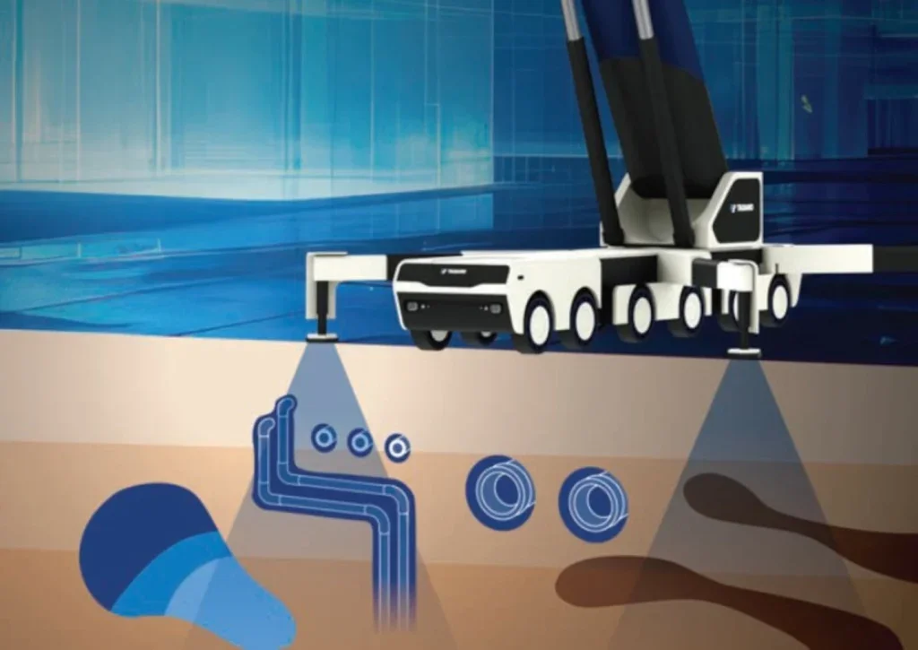
Tadano is working on a system where the crane itself forms the test weight. Called Ground Collapse Prevention it was unveiled at the CES 2025 exhibition which took place in Las Vegas in January. The CES (Consumer Electronics Show) is one of the biggest and most influential tech trade shows in the world.
The system evaluates ground stability for each worksite before crane operations begin. It combines ground property measurements, load analysis, and overturning prevention controls and therefore helps ensure the stability of the crane.
Using the crane’s own weight spot-by-spot ground stability is measured, under each outrigger, during the setup phase. On-board sensors measure the settlement at each outrigger over time. This establishes the ground property data – the relationship between pressure and ground movement. That relationship between load and settlement is analysed for each worksite.
During operation, the downward pressure exerted by each outrigger can be calculated. The system works out the crane’s overturning moment for all postures and load weight patterns, and hence the limits of safety on that particular soil. By combining multiple data points, the crane can stop operations before ground collapse occurs.
This approach, says Tadano, is most effective on soft ground surfaces. It is not applicable for paved roads or areas with underground cavities or buried pipes since the ground behaviour of such sites is much less predictable: voids can lead to sudden collapse with little or no prior warning. To enhance this technology Tadano is seeking partners specialising in crane-mountable groundpenetrating detectors.
KNOCK ON WOOD
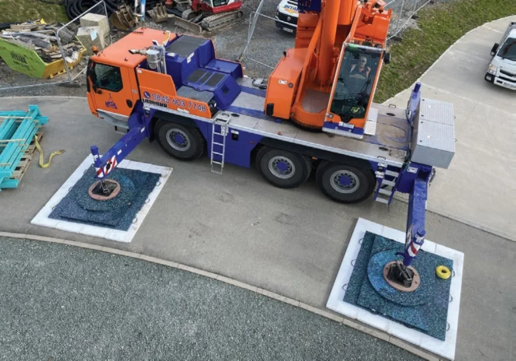
Once ground conditions, and lifting details, have been assessed crane users should have an idea of how much ground support they need under their crane’s outriggers; in other words, how large the outrigger pads used should be.
A simple division sum tells the size of pad required. After that the key decision is what material the should outrigger pad be made of: wood, steel, or synthetic?
Colin Ryder is operations manager of Stockport, UKbased Timbermat. The company supplies timber mats for all kinds of applications, crane mats and outrigger pads amongst them. “70 mm is the usual thickness,” he says. “We use Ekki, which is a tropical hardwood, and oak or beech sourced from Europe.
“All our supplies are FSI certified. They weigh from 370kg up to about 1.2 tonnes; we hire them or sell them – both methods are used by crane companies.”
Wood has been used as ground support for 5000 years or more and remains in high demand. Mat and Timber Services, a UKbased division of timber structure specialist Sarum Hardwood Structures, (itself a subsidiary of Dutch company Groot Lemmer), also supplies hardwood mats. Simon Lumley, operations manager there, confirms this. “Demand for wood has not declined,” he says. “Steel is an alternative but it is more expensive and heavier.”
Steel does have its fans; the third option, however, is to use synthetic pads.
Outrigger Pads, of Kidderminster, UK, specialises in High-Density Polyethylene (HDPE) spreader plates, outrigger pads, and crane mats.
“Our pads won’t splinter or corrode and have a very high resistance to vertical pressure,” says its outrigger specialist Sally Eades. “Coupled with the fact that it is waterproof, this significantly extends the products’ working lives compared to pads made of wood or metal. The material also has a degree of flexibility.”
And flexibility is important. A totally rigid pad, when set on uneven ground, will transmit all its load onto the few highest points of that ground, which may then compress or break. This rather defeats the original object of spreading the load. “HDPE pads adapt to the contours of uneven terrain,” she says, “but spring back to their original shape after use.”
Another advantage is that HDPE pads can be manufactured round, square or with recesses built-in to fit the shape of the outriggers.
The material is lightweight, easy to handle, and has excellent loadbearing capacities. Pads come with rope handles or with integrated steel bar handles; and, for safe transport and stowage, a galvanised stowage holster can be bolted on to the crane to carry them.
Outrigger Pads also offers a Multi Mat system, which is modular. The mats have tongue and groove edges which slide into each other. When stacked in layers, with a circular pad on the top, the weight of the crane forces the mats into the correct position and eliminates gaps.
DICA of Iowa, USA is a family-owned and operated company that specialises in making high-performance engineered outrigger and crane pads.
CEO Kris Koberg summarises the characteristics of each material. “Wood pads are prone to rot, splintering, and degradation, especially when exposed to moisture. This reduces their lifespan.
“Steel pads are robust but susceptible to rust and corrosion, particularly in harsh environments. Regular maintenance is required to keep them in good condition.
“Synthetic outrigger pads do not rot, splinter, or rust, so last longer with minimal maintenance. They are more expensive but their durability can lead to significant cost savings over time.”
Several pads can be laid on top of each other for added strength but it is important to understand, Koberg says, that stacked materials will not perform as well as a single, thicker layer due to the lack of shear connection between the layers. “Each layer behaves independently, which reduces the bearing area,” Koberg says. “For example, two stacked pieces of material of the same height as a single piece will be half as strong and will deflect four times more than the single layer of the combined thickness.”
DICA last year introduced a new concept, called LevelRight, which it claims is unique. It is an adjustable levelling pad. Setting an outrigger on sloping ground would be deeply inadvisable; clearly any support under the outrigger should be level. LevelRight is a two-part circular wedge; the two parts can be rotated against each other so that the top surface can be made horizontal even if the bottom surface is on a slope.
Users can adjust the angle from 0-10 degrees and adjust it in two planes up to five degrees. The circular LevelRight pad is 24 inches (60 cm) in diameter and will accept outrigger floats up to 20 inches (50 cm) square or 24 inches (60 cm) round. It has a rated capacity of 350,000 lbs (160 tonnes).
“When we first introduced a prototype of LevelRight the response was significant,” said Koberg. “It’s common for an operator to have to set up on uneven terrain but on a hard surface where it’s more difficult to manipulate the ground under the outrigger, LevelRight is the solution to ensure a safe and level setup.”
LevelRight is made of an artificial SafetyTech material, which is a proprietary durable engineered plastic, with DICA SafetyTexturing on the top and bottom surfaces. It also has a built-in bubble level to provide operators with confirmation when they have a level surface under their equipment’s outriggers.
“With LevelRight we wanted to make the right way of doing things an easy way of doing things,” said Kerry Koberg, sales director at DICA. “For crane applications using outrigger or crane pads LevelRight fits between the pad and the outrigger float to ensure the outrigger is placed on a flat and level surface.
“In situations where cribbing blocks are needed for extra height, LevelRight can be used as the base under our ProStack Cribbing Blocks to ensure the blocking is on a level surface.”
DICA also points out a curious vicious circle concerning rigging pads. For large-capacity cranes the rigging pads also need to be large – and therefore heavy. For cranes with a lifting capacity of, say, 100 tonnes the crane pads cannot be lifted or moved by hand. You will need, therefore, a crane to lift them. Happily, you have your large-capacity crane, on site, and in exactly the right place, and it could do just that – except that it does not have its rigging pads in place, and without its rigging mats in place it cannot lift its rigging mats into place! The crane should not be picking and placing outrigger pads unless its outriggers are supported by outrigger pads. We have a logistical everlasting regression.
A second, smaller crane to lift the pads would be an option, but an expensive one.
DICA suggests, instead, a second set of rigging pads that are lighter, and less cumbersome, than the permanent ones.
Its Heavy Duty SafetyTech pads, ranging from 36″ to 48″ in diameter, can be rolled into position by hand, by just one or two operators. The crane sets its outriggers on the temporary pads, uses them to set the permanent pads in position, then shifts its outriggers to these ones – and the apparently-impossible task of lifting yourself by your own bootstraps is accomplished!
Safely installing outriggers may seem simple but is actually a complex subject. As well as crane geometries and loadings it needs knowledge of geology which, when applied to building sites over unknown substrates, can be an inexact science.
Fortunately there is now an updated guide to best rigging pad practice: Virginia, USAheadquartered trade association, the SC&RA, at its Crane and Rigging Workshop in September last year, introduced a new member resource. It is called ‘A Guide to Outrigger Pad Materials, Selection and Usage.’ A taskforce has updated the document. The Guide provides information and best practices to the construction industry on the types and selection of supporting materials, such as pads, dunnage, etc., to minimise the outrigger bearing loads imposed on supporting surfaces during load handling activities. It promotes awareness of existing standards and regulations, lift planning preparation, supporting materials and types, and jobsite requirements. The SC&RA says that controlling entities, lift directors, site supervisors, or others who have responsibilities by standards or regulations for lift planning will find this guide helpful. Details of how to access the document are on the SC&RA website (scranet.org)
An outrigger pad has few or no moving parts. If it seems simple in comparison to the crane it is supporting, beware: it may well be the only thing that stands between your crane and catastrophe.
GROUND SUPPORT SYSTEM FOR 90 TONNE CABLE REELS FROM CADMAN CRANES
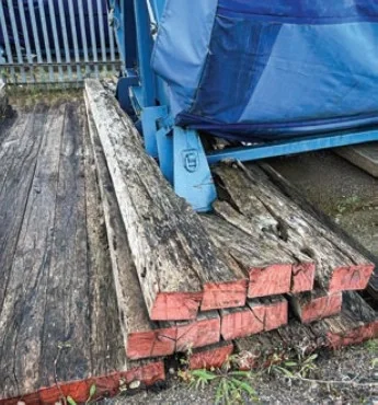
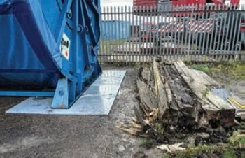
Galloper Offshore Wind Farm is a 353MW renewable energy project located 30km off the coast of Suffolk, generating enough green electricity to power 440,000 homes. The site’s Operations and Maintenance Facility at Harwich International Port, UK, stores six large cable reels that can be deployed in the event of offshore cable failures. However, these cable reels had been stored on timber mats for several years and the harsh marine environment had degraded the timbers, which needed replacement and a long-term solution installed in their place.
UK lifting solutions provider Cadman Cranes was appointed as Principal Contractor by global energy company RWE to design and install a new support system. The project involved managing several contractors and diverse trades to successfully deliver the contract in less than four weeks. The reels, weighing up to 90 tonnes, required the use of a very large crane positioned as close as possible. Due to the ongoing responsibility for the support system and the £1 million replacement value of each drum, an increase in insurance cover was required.
Project scope and execution
As Principal Contractor, Cadman Cranes was subject to the Construction Design Management (CDM) Regulations, overseeing multiple contractors and trades while ensuring the safe and efficient delivery of key tasks. The scope of work included lifting and storing the reels, removing and disposing of the degraded timber mats, preparing the ground, and designing and installing a new support system. This new system was required to be fi t-for-purpose and provide structural stability for many years to come.
The contract was fi xed-price and demanded rigorous levels of planning and project management to mitigate the higher levels of commercial risk compared to standard ‘daywork’ contracts typically used for lifting requirements. The existing timber supports required a more considered approach to disposal due to their age and wear. The team faced challenges in specifying how the mats could be safely removed to prepare the ground for the new system.
The ground below the crane position was uneven and required a groundworks contract before the main works could begin. Even after reconstruction, the area had such low ground bearing capacity that a massive system of timber mats was needed to support the crane. Ground preparation was essential to ensure the safety and stability of the lifting operations.
Resources and equipment
To achieve successful delivery Cadman Cranes implemented a range of specialised resources and equipment including:
- Inspection and certification of the client’s bespoke cable reel lifting system.
- A six-day Contract Lift with a 60-tonne mobile crane and a four-day Contract Lift with a 500-tonne mobile crane.
- Groundwork crews using type 1 material, rollers, and excavators to prepare the ground below the new support system.
- Structural analysis and certifi cation of the proposed support system.
- Delivery and installation of 52 galvanised steel plates (2m x 1m x 25mm) and 12 neoprene bridge-wearing pads.
- Design and installation of a crane support mat comprising 72 hardwood crane pads (5m x 1m x 150mm).
- An electric counterbalance forklift, magnetic lifting device, lorry loader, and pick-up vehicles.
- A dedicated team including six crane operatives, a project supervisor, and a project manager.
Through planning, engineering, and project management, Cadman says it delivered a robust solution for the Galloper Offshore Wind Farm’s cable storage needs. It says the new support system ensures the stability of the reels for many years, safeguarding this critical infrastructure and supporting the continued operation of one of the UK’s key renewable energy projects.