French contractor Dumez GTM has a reputation for inventive construction technique. Its work on the dramatic new Rion-Antirion bridge in western Greece is no exception and includes new crane methodology worked up with manufacturers Potain and Manitowoc.
Dumez GTM is the lead firm in the Gefyra Consortium, which includes six Greek contractors. This group is not only building what will be one of the world’s great crossing, but is also part owner of the client, also called Gefyra, which has a 35 year BOT (build, own, transfer) concession from the Greek government for the 2.8km long crossing.
Earthquakes and deep seas make it a difficult job but the design and construction solutions – the consortium is responsible for both – are inventive.
Among them is a special trolley system to shift sideways the top tower section of a fully operational Potain MD 600 tower crane, including jib, cabin and counterweight.
Elsewhere satellite controls will be used for positioning a precision dredge barge which uses a Manitowoc 888 ringer-mounted lattice boom crane as its main tool.
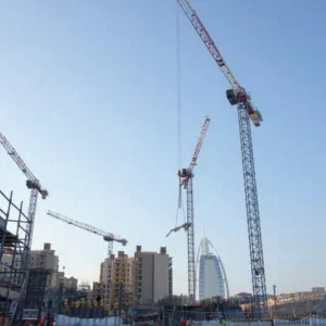
And the production yard for four huge bridge pier bases is dominated by a logistically sophisticated dance of tower cranes on concreting and precast. Vital for this has been Potain’s computerised anti-collision system which prevents jibs clashing in the site’s limited airspace.
The cable stay bridge will be a record breaker, with a 2.25km continuous deck much exceeding the 998m main span Tatara in Japan. Admittedly Rion-Antirion will not be a single span – four hefty pylons support the main crossing – but it will be a continuous deck ‘hanging’ with no joints or breaks between the viaducts on either side. A few light seismic movement dampers at each pier will be the only connections.
The three central spans of the bridge will each be 560m and back spans 286m. These join approach viaducts of 380m on the south and 228m on the north Antirion side. The deck will be composite steel and concrete box 25m wide supporting a dual two lane highway.
The bridge will sit across a narrow entrance to the Gulf of Corinth, the sea separating the Peloponnese from mainland Greece. Ferries have plied their trade here for centuries, but plans for a western highway linking the port of Igoumenitsa to the south require increased crossing capacity. The road will join the new PATHE highway connecting the Peloponnesian port of Patras to Athens and the northeast.
Dumez-GTM designers face not only great length, winds and strong sea currents in 65m deep water but regular earthquakes. Shakes are frequent and hit above Richter 7 every few decades.
The bridge must also cope with an extraordinary potential movement of 2m sideways at its end point during a 120 year design life.
“Put simply, the Peloponnese land mass is moving eastwards while the mainland goes west,” explains Gilles de Maublanc, Gefyra’s project manager at the site. For the same reason the channel itself contains no bedrock because it has been ground down. Soils are hundreds of metres deep and could liquefy in earthquakes. Rather than fight nature, the consortium has decided to let the bridge ‘give’ a little. Main towers will simply sit flat on the seabed with no piles, able to move freely if the ground shakes. Gravity holds them.
However each pylon must be more than 240m high. Of this, 65m is under water, 50m clears above sea level for the deck and another 80m makes up the four pylon legs for each tower which carry the cables. Anchoring points for the cable add a final 35m height.
Without fixed foundations such high towers could overturn and so they will have enormous circular bases, 90m in diameter and about 7m high. A tapering central cylinder then rises to deck level giving the tower base the shape of a gigantic chess pawn. The pawn’s neck is an octagonal straight tube to a ‘head’ formed by a complex four-sided widening out to deck level, where a platform supports tower legs.
Tower base construction uses North Sea oil platform techniques, manufacturing units onshore for float-out later. Gefyra formed a dry dock on the north side of the strait using sheet piled cellular coffer dams. There is room in the 200m long dock for two caissons.
The surrounding yard is currently organised to store and supply components and materials for caissons, though later it will switch to production of the steel frame and concrete deck units.
Three rail-mounted Potain MD 305s, rated at 300tm, feed the dock while two other fixed MD305s, work the precast yard and the stockpile of rebar. A Liebherr ECH 180, previously used on the Athens metro, is also used for precast. Two of the rail mounted units have 55m jibs and are working with 24.3m and 34.3m underhook heights respectively. The third has a 50m jib and works with an underhook height of 24.3m.
For the precast yard a jib length of 55m is used and an underhook height of 26m, while the unit at the rebar stockpile has a 55m jib and is working with 47m underhook and a 58m mast.
Construction is tightly sequenced in the two level drydock which was sealed with a temporary coffer dam when work began last summer. Lower pier base is made in the upper 10m deep level of the dock and then floated into the lower 12m section for completion and start of the narrower central cone.
For the base a 600tm Potain MD 600 with a 60m jib is mounted centrally. The crane, secured by four guy ropes, is used to lift rebar and formwork. Average lifts are in the region of 12t and at a working speed of 60m/min.
In the lower dock a second phase of construction begins on the narrower cone of the pylon. A shorter jib is now used, just 50m. One of the MD 305s makes the alteration, also lifting in four mast sections to raise the underhook height to 68m from 45m.
Following a float out for the first unit in September 2000, the contractor has saved resources by using the partly formed second caisson itself to re-seal the dock. When this unit leaves shortly the third base unit will take its place while a fourth begins at the top.
To save time Dumez has prepared the small core of the final caisson in a space to one side of the drydock. A crane mounting base was concreted into a small circular reinforcement cage. With the first sections of the final MD 600 already in place this will be skidded by jacks into full construction position immediately after the next float out takes place.
Meanwhile the first unit is in the ‘wetdock’, a dredged sea area close to shore. Construction of the pylon continues with the MD 600 lifting rebar and also concrete using a 3m3 bucket. This option proved better than the original plan to pump from onshore.
As the pylon cone grows using climbing formwork, the unit is slowly sunk by water ballast pumped into its hollow compartments. Water is also used to balance the construction and keep it within 1° of vertical which is important for the crane operation.
When the cone is 57m high the unit will be moved to a prepared position in the channel, with the crane, by now 115m high, partly enclosed enclosed within the cone.
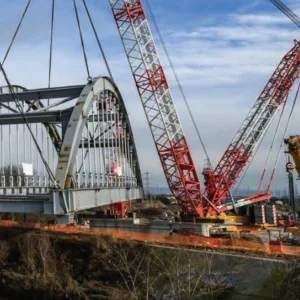
While all this has been happening the big barge has been preparing the pier sites. This barge was brought from the Second Severn crossing in the UK where it had been used as a jack-up barge. At Rion it has been fitted with huge weighted chains which act as tension legs to keep it stable in such deep water, since it is not practical to jack it up 65m. A smaller multiple engined barge helps position it accurately before anchoring.
A brand new Manitowoc 888 mounted on a ringer on board serves multiple functions. First comes dredging, levelling the seafloor 65m down with a bucket grab. It lifts and controls a massive Menck hydraulic hammer driving 2m diameter steel tubes into the seabed for ground improvement against seismicity.
Then the Manitowoc lifts in gravel for a special delivery tube, controlled by a distribution frame at the back of the barge. An even seabed layer 3m thick is prepared for the caisson.
Later tasks for the barge include feeding materials and equipment to the Potain working on an octagonal section of the pylon before the complex widening out for the deck level. It will also hand up deck sections when superstructure work commences. A Manitowoc 4100 on a smaller barge also assists.
At this point the MD 600 will still be working from its central position in the pylon but as the ‘head’ reaches completion it must move sideways to allow the deck to be installed. Potain helped the contractor to devise a special frame attached to tower section. This can jack up the whole crane, transfer its load onto a wheeled trolley on specially fitted rails, and move it some 23m for lowering onto a new base fixing. Pins are refitted to begin operations. The remaining mast in the pier core is dismantled by the MD 600 itself, the units re-used to help the crane climb again as the four main pier legs are constructed.
Each crane reaches an eventual freestanding height of 127m, or nearly 180m above sea level. At this height the crane must lift a 40t steel and concrete cap, which it can handle at a 17m radius with a second trolley installed.
Work is due to finish in 2004 when 2,800,000 cars, 760,000 trucks and 170,000 coaches are expected to cross in the first year.