When the original cableways the new bridge collapsed, F&M Mafco was called in to supply a temporary alternative lifting solution for the construction work.
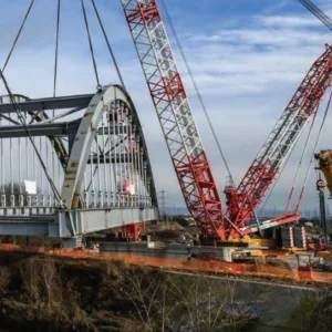
This took the form of a specially designed derrick crane system, before new cableways, using tower crane structures, were installed to lift and move the materials needed to build the 1,900ft-long Colorado River Bridge.
US Route 93 is a major commercial corridor between the states of Arizona, Nevada and Utah, and is on the North American Free Trade Agreement route between Mexico and Canada. The old route used the top of the Hoover Dam as a crossing over the river, but was inadequate for this purpose as traffic volumes, including through-traffic and trucks, combined with the layout of Route 93, resulted in low travel speeds, poor visibility, sharp turns and the potential for a major accident.
The new route, featuring a bridge with a concrete deck arch over the river, has been devised as a means to remove trucks and through-traffic from the top of the dam, and minimize the risk of pedestrian-vehicle accidents, stop the bottleneck of interstate and international commerce and reduce travel times in the area.
Construction of the Colorado River Bridge crossing was to be carried out by a cableway system, which would take on a pivotal role in the movement of construction materials across the entire canyon, a distance of almost 2,500ft. However, the original cableways collapsed in September 2006, delaying completion of the project and providing contractor Obayashi Corporation with the problem of not having another cableway available to replace the collapsed system.
Obayashi turned to Ohio-based heavy mechanical contractor F&M Mafco to provide a system to replace the collapsed cableways while a new cableway was designed and fabricated by Canada’s Somerset Engineering. F&M Mafco said the geography of the site and the long lift radiuses meant traditional lifting techniques, using large crawlers and other cranes, were not practical as the required capacities at a radius of 330ft could not be reached.
Instead, F&M Mafco opted to erect an American S-70 stiffleg derrick and American 550 hoist on the Arizona side of the river in order to get construction of the crossing back on track. Even this solution was not ideal, F&M Mafco said, as in its standard configuration, the derrick did not have the reach required to lift the 55 USt loads at 330ft needed to set the outer piers.
F&M Mafco decided to ship in its own complete 600 USt boom from Scotland, in order to increase the derrick’s capacity to handle the work. While the boom was in transit, Somerset Engineering was employed to prepare the derrick in order to handle the boom, including designing the boom suspension and redesigning the boom base to fit the horizontal strut of the S-70. An 80ft jib was also employed in order to carry out long radius lifts.
In total, shipment, fabrication of components, engineering load charts and site preparation took around 120 days. After erection and load testing, the derrick was used for around 20 hours per day to set the piers, caps and girder beams on the Arizona side, before, in late September 2007, it was dismantled and replaced by the new cableway.
F&M Mafco was also involved in supplying the two cableways that replaced the original cableways that collapsed. The Somerset Engineering designed system featured four 335ft-tall towers, situated in pairs either side of the canyon.
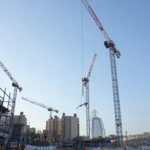
The cableway is a highline system that uses the pairs of tower cranes on either side of the canyon to form dual high lines. Once the high lines are erected, the entire length of the bridge becomes accessible to the crane hook for delivering materials for the main arch, columns and superstructure of the bridge.
The towers were designed to luff 30ft in each direction to allow precise positioning of loads, with four hoists used for luffing, or moving side to side, each of the towers. An additional four hoists were used to take up the tension of the 3in wire ropes spanning the canyon, with a further two hoists used to pull the trolley in and out, and two used for raising and lowering the load block. A final two small hoists were used to hold the tension on the trolley line.
A total of 80,000ft of wire rope and pendants were supplied for the cableways, and various rigging blocks from 65 USt to 200 USt capacity were used.


