A temporary pedestrian suspension bridge was constructed across the gorge at Warragamba, near Sydney, in the 1950s to provide workers with ready access to both sides during the construction of a dam at the site.
While the bridge had steadily deteriorated with age, a bushfire in 2001 affected at least two-thirds of the bridge and accelerated the need to render the bridge safe. Any method chosen had to ensure that no debris entered the river 80m below the bridge, and that trees and vegetation on either side of the gorge were not damaged during the work.
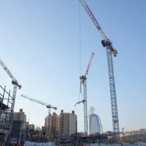
The initial plan was to span the gorge with two tower cranes: a Favco M1280D and a Favco M1680D both owned by Marr Contracting. Those cranes would support a working platform built to a Marr Contracting design by Metropolitan Demolitions, successful contractors to the Sydney Catchment Authority for the project. The use of tower cranes would mean that all work took place above the tree and vegetation level.
The working platform measured 7.0m x 3.5m, and had a working capacity of 5t. It was hung from the crane with a C-section arm made using 1120mm square boom sections from a 45t Lorain crawler crane. The number of vertical sections in the arm could be varied from 6m-16m, depending on the distance between the top of the suspension rope and the point at which the deck was working. This meant that the overall weight could be minimised when the platform was furthest from the crane supporting it, and the separation between the suspension ropes and the deck was the smallest. The weight of a fully laden platform could be as much as 11t, depending on the number of boom sections in the drop arm.
When Metropolitan Demolitions was able to establish on site and survey the exact locations of the crane bases, it was determined that the tower cranes would be unable to lift the platform across the full width of the gorge required to dismantle the bridge. An alternative location, founding Marr Contracting’s Favco on a rock ledge on the eastern slope of the gorge using that company’s Favco M1680D tower crane working from above, was ruled out when testing of the rock indicated that it did not have the required strength to support the crane.
The option of locating the crane on a narrow service road at the base of the gorge was also ruled out, as it was not possible to restrict access on this road for the duration required for the demolition project.

It took three cranes to hang the basket over the entire width of the gorge
The plan ultimately involved an unusual combination of a large tower crane, large lattice boom truck crane and large all terrain crane as the main lifting machines. The M1680D tower crane on the eastern side of the gorge, where it could cover a radius of 80 metres, and a Link-Belt HC268 lattice boom truck crane on the service road at the base of the gorge. Equipped with a fixed fly jib, it could cover a radius of 90m, although it was unable to handle the large working platform at that radius and used progressively smaller man baskets until it reached the centre of the bridge.
There was a narrow roadway to the bottom of the gorge on the western side, and it was determined that a 225t Liebherr LTM 1225 hydraulic all terrain crane from Gillespies Crane Services could access this road, and when equipped with a luffing fly jib it could reach the remaining span of the bridge. This crane covered a radius of 50m, with 68m under the hook, and used the working platform at a safe working load of 6t.

The cranes were set up on either side of the gorge
The roadway was so narrow and winding that the crane needed to raise the centre two wheels to be able to manoeuvre, and in many places either side of the crane brushed against guideposts.
The structural steel framed working platform was encapsulated with shade cloth around its perimeter to contain all the demolition material and prevent anything from falling in to the river below. Men worked from the platform, removing timber bridge sections and stacking them in the working basket. Prior to its safe working load being reached, the platform was returned to compounds on either side of the gorge to unload demolition materials into skips.

Workers in the basket collected and dismantled sections of the bridge by hand
Once the deck was removed, Marr Contracting used three independent winches, each with a 12t line pull, to winch the eight 54mm diameter cables back to the eastern embankment. Each cable had a total span of 240m.
The project took 16 weeks to complete, the last three of which were spent shotblasting and painting the 20m high structural steel east tower that supported the suspension cables.
Bridge lift

Gillespies LTM 1400 and LTM 1250/1 placing the third beam on its headstocks
When a busway bridge was being built over Toongabbie Creek in the Sydney suburb of Wentworthville, the beams for the crossing were placed from the nearby Old Windsor Road. While difficult in terms of traffic management, this job was par for the course for a competent crane hirer with bridge experience.
However, to later build a new walkway bridge almost parallel to the busway bridge but further from the highway, it was no longer possible to reach the site from the highway, especially as the heaviest of the beams weighed 80t. Four beams needed to be placed: a 17m and a 14.98m beam at either abutment, and two 30m beams in the centre.
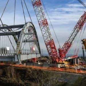
Gillespies Crane Services offered a novel solution using its 250t capacity Liebherr LTM 1250/1 and 400t capacity LTM 1400, often working on half outriggers from the busway bridge.
The positioning of the cranes was critical – constrained on the one hand by the capacity of the busway bridge and on the other hand by the need to stay within radius on a project where the cranes worked at close to their safe working load for much of the time. The busway also provided the means for a truck and trailer to deliver the beams close to the cranes.
Four beams needed to be placed and the first was lifted by the LTM 1400, working from the opposite side of the bridge piles to the busway. It lifted the 56t beam over the back of the crane at a 20m radius, then slewed slightly and boomed up to reduce the radius as it placed the beam to span the first gap.
For the second beam the LTM 1250/1 worked from the busway bridge, and the positioning of the rear outriggers over the bridge piles was critical. The LTM 1400 maintained its position from the first lift and again worked at a 20m radius, while the LTM 1250/1 worked at a 12m radius. A truck backed the beam onto the busway bridge, where both cranes picked the beam up and slewed to place it over the headstocks of the new bridge.
The 400t crane then moved onto the busway for the third beam. A truck towed the beam trailer into position behind the crane, which then picked up one end of the beam from the truck and started to slew with it. A second truck entered the bridge and pushed the steerable trailer that supported the remaining end of the beam towards the LTM 1400, until it was in range of the LTM 1250, once set into its final position.
The second truck then backed off the bridge to allow the 250t crane to move into position. Then it picked up the other end of the beam, slewed to position the beam over the piers, and coordinated with the 400t crane to lower the beam into position. The cranes were positioned such that they did not need to change radius during this already complex lift.
This LTM 1400 remained in position for the final lift, where it placed the final beam at a 16m radius. While the lift itself was straightforward, the outriggers needed to be placed with centimetre precision to control the loading on the busway bridge.
The choreographing of the trucks and cranes to complete this lift programme would have done credit to a ballet production, and it will improve pedestrian and cyclist access in the Wentworthville area for years to come.


