One of the best known names in specialist heavylifting is Rigging Management Systems AB (RMS) of Skövde, Sweden. Less well known internationally – in spite of its award-winning work on the Heidrun drilling rig in 1995 – is the company that has grown out of its Norwegian subsidiary, Transrig.
RMS set up RMS Norge in Norway in 1981 with Arne Østraat as managing director. In 1989 Østraat took over RMS’s shareholding and, with the support of Sarens de Coster of Belgium, took over the company and renamed it Transrig. RMS and Transrig maintained close relations, however, and the two companies often work together, both in Scandinavia and elsewhere.
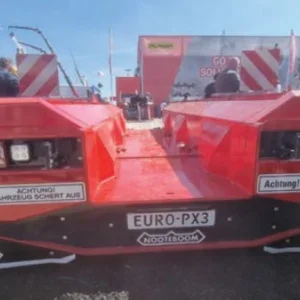
Where required, Transrig uses RMS’s patented lifting tower system, and cranes and self-propelled modular trailers from Sarens. Transrig’s own equipment includes a computerised ballast monitor and control system and a 4 x 100t lifting tower system, custom designed for lifts on oil platforms in operation.
Last September Transrig conducted nearly 50 load-out operations moving weights up to 12,000t. Two of its more noteworthy projects were carried out in the same month.
Oseberg Sør drilling rig
“One of the most complex lifting operations that has been performed at a Norwegian offshore fabrication yard,” is how Transrig describes the installation of an 1,800t drilling rig onto a 20m-high Mud module. The dimension of the drilling rig for the Oseberg Sør platform was 20m x 12.5m x 85m – in other words a very high module with a very small base.
The installation method was developed by Transrig in close co-operation with the fabrication yard, Aker Stord. A key goal was to eliminate the costly disassembly and re-assembly of the drilling rig that would have been necessary for a conventional installation using cranes. Being able to install the drilling rig as one unit also meant that it could be tested prior to installation and not have to be re-tested afterwards.
The drilling rig was delivered to the yard on a transport barge. Transrig used four rows of 18 axlelines of self-propelled platform trailers, supplied by Sarens, to drive the drilling rig onshore and 2km to the installation site. Due to the height of the drilling rig, attention had to be paid to keep the trailer platform horizontal, regardless of the ground slope.
At the installation site the drilling rig was jacked up using a set of climbing jacks while a second set of jacks was used for backup. The jacking operation was needed to install the lifting towers and beams. Once the lifting towers were installed it took three hours to lift the drilling rig up 20m. The lifting operation was done using four 750t lifting towers supplied by RMS, which also supplied the operators. The main advantage of these push-up towers is that the load is always firmly supported on the ground on a steel column during the lift, rather than suspended from wires or strands, thus eliminating the risk of horizontal sway.
When the top of the lifting beams was flush with the top of the skidtrack on the Mud module, link beams were installed between the lifting beams and the Mud module. The drilling rig was skidded on Teflon pads across the lifting beams and the linkbeams onto the permanent skidbeams. The skidding operation, across 50m, took less than four hours.
Once in final position the drilling rig was jacked up to remove the temporary skidpads that had been used to protect the permanent pads.
Transrig is now working on the detailed engineering for the trailer load-out of a 10,500t deck and a 105m-high, 5,000t module during the first half of 2000.
Âsgard B Riser Balcony
Also in September, Transrig performed a trailer load-out of a module weighing 3,000t over a length of 80m at Kvaerner’s fabrication yard in Egersund, Norway. Although the weight and dimensions of this module are not unusual, the operation presented a special challenge to the engineering team. The module was a Riser Balcony designed to be suspended from the side of a semi-submersible oil rig where the side of the rig would stiffen the module. During the trailer transport the module had only a 1200mm-deep beam to provide stiffness along the 80m-long structure. To add to this challenge the module was outfitted with pipelines that would not withstand a deflection in excess of 100mm over its length.
Together with the engineering team from the fabrication yard, Transrig developed a trailer arrangement that hydraulically balanced each transverse frame of the module. This was then added to a computer model to estimate the module deflections during the load-out. The conclusion of this analysis was to use two rows of 58 axlelines split into four hydraulic groups. To optimise the load balancing, several axlelines were hydraulically disconnected during the move.
Before the load-out the module had already been moved out of the fabrication shop to allow the final outfitting. This site move included several 90O turns before driving down a slope to the outfitting site. The module weighed close to 2,000t during this operation but because of its length it required a similar number of axlelines to the load-out.
On the day of the load-out the trailers’ hydraulic suspension was used to lift the module off the fabrication supports. Once the module was supported on the trailers, the deflection of the module was checked and found to be well within the specified tolerance. The actual deflections of the module reflected the results of the computer model.
During the load-out, deflection was continuously monitored. The hydraulic suspension took care of the uneven areas of the ground as well as passing over the bridges to the barge. By the end of the shift the module could be safely lowered onto the barge grillage and the trailers demobilised.


