When you live on a small island the scope of equipment at your disposal can be limited and ingenuity may be called upon to make the best of it. This has been demonstrated by Hawaiian Crane & Rigging in the past. On this project, however, the loads to be lifted weighed a mere 36t. With cranes capable of lifting 300t and 180t ready and available, one would have thought that the muscle power on site would make the job relatively straightforward. Not so.
The lifting contractor was called upon to place seven 43m-span bridge girders at the Historic Aiea Sugar Mill site on the island of Oahu in late April. The initial plan was to deploy two cranes and tandem lift the girders into place. But the week before the operation, it was revealed that a design change meant that the main contractor, Royal Contracting, could not provide the space on site that Hawaiian needed. There was just room – and only just – for one crane and the load to be lifted, but not even the 300 tonner was strong enough to set girders itself, given the radius at which it had to lift. The other crane could be no nearer than over the other side of an embanked bridge abutment.
The lifts were on the critical path. Hawaiian’s engineering team, under director of engineering Kerwin Chong, responded by designing, fabricating, load-testing and implementing a girder launching system. And it did this in just three days.
The girder launching system was designed to meet four criteria:
• The system had to allow one crane to pass the load over to the other. As one crane put the load out and reached the limit of its chart, the other crane would take over, without unhooking the load, and bring the load in. As one crane loses strength, the other would gain it.
•The crane that begins by taking the weight of the load had to have two lines configured in such a way that as one line was slackened, the load moved to the other line, so that eventually this crane was lifting only one end of the girder. At that point, the second crane would have taken over the load of that end of the girder.
• The single line pull of the winch was not enough to handle the vectoral weight of the girder, so multiple parts of line had to be handled.
• Hoist lines had to be kept within the manufacturers’ fleet angle requirements.
An Excel spreadsheet was set up and the load sharing was analysed for every foot of travel, all the way from delivery to the final setting of the last girder. Computer simulations were also used to support the calculations.
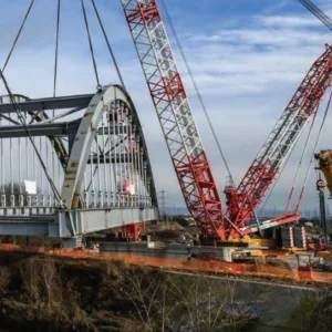
The cranes used were a 300t-rated Krupp KMK 7300 all-terrain, set up on one side of the embankment and a 180t Link-Belt HC 258 lattice boom truck crane on the other side. The Krupp telescoped out 52m of main boom and reached across a radius of 40m to hook up to the first girder, though took none of the load at this stage. The Link-Belt, with 46m of boom, had both of its lines hooked to the girder.
Hawaiian’s director of operations Parker McKeague takes up the story: ‘Once the Link-Belt HC 258 had the girder off the trailer, our operator had to be very careful lifting the girder using the double line pick. The Link-Belt started his swing while the Krupp boomed up and followed the girder. When the Krupp had the capacity, the Link-Belt made a controlled release of the number one line, eventually giving the Krupp half its load, while the Link-Belt’s number two line held the other half of the load.
‘The operation needed to be very tightly orchestrated. The Link-Belt operator had to be very careful while relaxing the number one line. As the Link-Belt was releasing the load, the Krupp needed to be simultaneously booming up. Both crane operators watched their load indicators carefully to ensure that neither crane was ever out of capacity.’ McKeague concludes: ‘The job went without a hitch. At the zenith of the job we were setting girders in six minute cycles.’ McKeague and Chong expressed their thanks to Alan Barnhart of Barnhart Crane & Rigging for allowing Hawaiian Crane & Rigging to bastardise his ‘bear paw’ concept. Barnhart’s ‘bear paw’ is a triangle with one hole at the top and three on the bottom, like a mini tri-spreader. Hawaiian’s variation had only two holes on the bottom. In either case, the function is to keep hoist lines vertical, while being able to use multiple parts of line on one leg for load adjustments.