The previous two articles in this series have described some of the effects of wire rope faults and how to detect them. Here, we complete the list of causes of damage.
Birdcaging
A birdcage is a short section of rope in which the outer strands are much longer than the rope and therefore “stand up”. Birdcages are normally formed when a wire rope is opened up by twisting or by being twisted around its own axis. In an opened up (unlaid) condition, the outer strands are too long for the rope length, and the “superfluous” strand length is brought to one point by a sheave. This is why birdcages are often found at the end of the sheave travel.
A shortening of the rope can also create too much strand length for the inner rope elements.
The worst situation arises if a rotation resistant rope is twisted in the opening direction. This causes a lengthening of the outer layer and at the same time a shortening of the core. This is why rotation resistant ropes are so sensitive to being twisted by external mechanisms (for example, fleet angles).
Birdcages can also be created by dragging a rope through a tight sheave. If a non rotation resistant or semi rotation resistant rope is operated with a swivel, the rope will unlay. Unlaid rope sections will then travel over sheaves. The result often is a birdcage or several birdcages at the other end of the rope.
Contrary to common belief, 99.5% of all birdcages are not created by shock-loads.
Damage from the sheave
If a steel wire rope enters a sheave under a fleet angle, it will first touch the groove flange. It will then partly roll down, partly slide down into the bottom of the groove. This mechanism will twist the rope, leading to the torsional problems described in the previous sections. It will also lead to increased wear, both on the surface of the wire rope and on the flange of the sheave.
Both the amount of twist and the amount of wear can be reduced by lubricating the wire rope and by opening up the groove throat angle (e.g. to 60°). Contrary to common belief, a throat angle of 60° poses less danger of the rope jumping a sheave than a throat angle of 45°.
A tight or stuck sheave might create birdcages or severely deform the outer wires or strands of the rope. Often martensite is formed on the wire surfaces. If, on the other hand, the groove diameter is much bigger than the rope diameter, the groove will not support the rope sufficiently and create very high local pressure, leading to premature wire failures.
If a long end of a broken outer wire catches and is bent across its neighbouring strands, it will easily get caught between the wire rope and the sheave causing nicking damage. This is especially relevant to Langs lay ropes where the exposed wire ends are always long.
Negative imprints in sheave grooves can be created by different mechanisms. If, for example, the circumference of the sheave at the bottom of the groove is a multiple of the strand distance in the bent condition of the rope, then during every revolution of the sheave, the same points in the groove will be hit by strand crowns, whereas the neighbouring zones will not be subjected to wear.
An indication for such a mechanism is a lubricant deposition at regular intervals on the flanges of the sheave. Continuous load changes lead to continuous changes in lay length. Therefore, ropes with varying loads are less likely to produce negative imprints.
Imprints will normally not harm the rope that created them. But the replacement rope will be damaged by the imprints, even if it is of the same design. Imprints can not always be avoided but can be delayed by hardening the grooves. Lubrication and slight rope rotation will also help avoid the formation of negative imprints.
As opposed to conventional steel wire ropes, swaged ropes have no crowns and valleys and will therefore normally not create negative imprints.
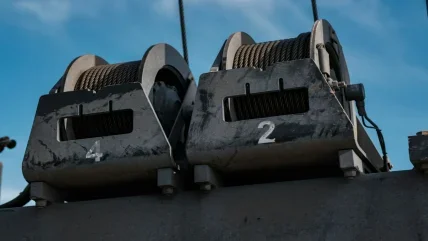
Damage from the drum
Left hand drums should operate with a right hand rope. Right hand drums should operate with a left hand rope. A violation of this rule might lead to rope twist and structural damage.
On a multi layer drum with special grooving, the crossover zones are arranged parallel to the drum axis. If the wear pattern shows that the crossover zones are inclined, the rope diameter is either too big or too small with respect to the drum pitch. Under these conditions, the rope will always cross over a bit earlier or later with every consecutive wrap.
If the fleet angle of the rope versus the drum groove is too big, the rope will either be pulled against a neighbouring wrap or against the flange of the drum groove. In both cases, the rope surface will be damaged.
Damage caused by multi layer spooling can be reduced by using Langs lay ropes with compacted outer strands. Hammered (swaged) ropes are especially suitable.
In multi layer spooling, drums with Lebus-type grooving have proven to be far superior to drums with helical grooving.
In multi layer spooling, a good pretension of the lower rope layers on the drum is essential. Lack of pretension can lead to severe wire rope damage.
In the worst case, the rope might be pulled in between the lower layers during lifting. During subsequent lowering of the load, the rope might not spool off the drum, thereby reversing the load movement.
Under high tension, a rope tends to be as round as possible. With no load, a rope can be deformed and flattened much more easily. Highly tensioned upper layers will therefore severely damage loose (and therefore vulnerable) lower layers.
If a load is applied to a steel wire rope, the rope will get longer. It will therefore slip on the first wraps of the drum, creating wear both on the rope and on the drum. If the load is always applied at the same location, the wear will concentrate in one spot. Shortening the rope (drum crops) or lengthening the rope will spread the wear and improve the situation.
In multi layer spooling, small diameter differences between two ropes might add up to considerable length differences being spooled onto otherwise identical drums. Therefore, steel wire ropes operating together should be ordered as a “matched pair”. They should have only very little differences in diameter.
Other phenomena
* Manganese-sulphite balls in the wire structure are extremely hard and do not deform in the wire drawing process. They often appear on the surface of fatigue breaks because wires will trend to fail in sections already weakened by such inclusions.
* The fracture zone of a wire destroyed through severe bending (very low cycle fatigue) will look like split wood.
* The fracture surface of a rope wire destroyed by pure torsion will look like an old 33 rpm LP record.
Rope geometry faults
* Loop formations can be (but may not be) caused by insufficient clearance between the wires in the strand. Lack of clearance will prevent these wires from moving relative to their neighbours, causing overloading and yield.
If the diameter of the steel core of the rope is too small, the outer strands will not have sufficient clearance, and inter-strand nicking will occur. A lack of clearance will considerably reduce the rope’s fatigue life.


