Grove’s new crane consists of a six-section telescoping mast up to 81m long, mounted on a standard semi-trailer. Four spreaders at the top of the mast attach by folding bars to four outriggers at the base of the crane. The crane is expected to be able to raise 70t (77 US tons) to 120m high.

The GTK 1100 finishes the job
The idea of bracing a slim tower can be traced back to a unique crane design developed at the beginning of the 1970’s. At that time Schmidt-Tychsen built rail-travelling revolving luffing derrick cranes, providing the maximum available lifting capacity for boiler house construction in Germany. Equipped with 92m main boom and 40m luffing jib, the DWD1800/1500 could lift up to 35t to 130m height but not the required 100t at the Weisweiler power station project in 1972.

Schmidt-Tychsen DWD 1800/1500 pylon-crane at work in the middle of the Weisweiler boiler house under construction in 1972. Note the pendants leading down from the outrigger edges.

Overview drawing of the specially modified Schmidt-Tychsen DWD 1800/1500 mounted in top of the 1.5m diameter tower with bottom climbing facility working inside the boiler house framework of KW Weisweiler. The crane climbed up 130m and still lift 100t with 44m boom.
In order to meet the demands of this project, Schmidt-Tychsen designed a unique modification. The complete base crane with 40m boom superstructure, 80t counterweight, turntable and outriggers was fitted on a slim 1.5m diameter tubular tower, which could be jacked up by inserting 6m sections through a bottom climbing system. The eight standard outriggers of the crane were connected with tension pendants in order to stabilise the tower, similar to the pendants connected to the four spreader arms at the turntable of the GTK 1100.
However in contrast to the Grove concept, the guy lines were connected to concrete foundations at the boiler house basement. Furthermore, every 14m the tower had to be tied with horizontal bracings to the boiler house columns. Located in the centre of the 28m x 28m boiler house frame work, the Schmidt-Tychsen crane was jacked up following the erection process of the steel frame work and could lift prefabricated sections weighing up to 100t to the full height of the boiler house.

GCI 5400 set-up – transport position

GCI 5400 set up – lattice boom rises

GCI 5400 set up – lattice boom raised

GCI 5400 set up – telescopic boom extends
In the 1970s Ontario, Canada-based GCI Manufacturing Inc. developed a series of unusual trailer mounted self-erecting tower cranes. While the bigger one, the GCI 5402, reached a boom pivot height of 42.6m using a four-sectioned telescoping tower carrying a lattice boom upper crane for a tip height of 72m, the smaller unit GCI 5400 was equipped with a Grove telescopic boom upper, with 27.3t capacity at 52m height, and 3t at 78m tip height with fixed fly jib extension.
For easy transportation the whole crane was mounted on one trailer and could be set up in just 17 minutes, using self rigging devices. Even today several veteran units are working in the fleet of mobile crane rental companies, specially serving narrow construction sites in North America.
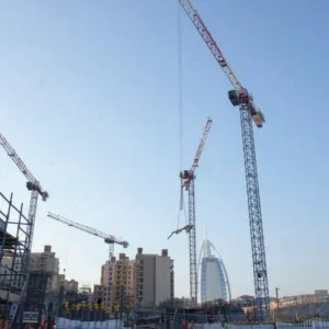
Designing for wind farms
Today the increasing height and weight of wind turbine installations poses a new challenge for mobile crane manufacturers. The traditional response to this problem has been to increase the size of bottom slewing cranes, at the cost of raising transport expenses. Ordinary tower cranes are ruled out due to their lack of capacity or by their long set up procedure and site preparation requirements.
The main task can be described as developing a crane that quickly reaches the required height and provides huge lifting capacity, on a very limited radius. Manitowoc’s synergy of Potain’s experience building self-erectors and Grove’s background in telescopic boom cranes, has given it a head start in rising to this task.
The GTK 1100 design, first shown as design studies in 2006, and to be revealed in prototype form at Bauma, draws on both these knowledge sets. Originally invented by a German crane rental company, the machine’s patent was bought by Grove and developed with help from Potain and Manitowoc.

Diagram of GTK 1100 raising itself

GTK 1100 when erected
Nacelles used on the current generation of 2mW wind turbines weigh around 65t and may need to be lifted to 85-100m. At windfarm construction sites outreach is not as essential as lifting height, and set up time and crane transportation should be as economical as possible.
The GTK 1100 is equipped with a six section telescoping vertical tower which extends to a height of 81m, topped with a Grove 60m telescopic boom superstructure, mounted on a turntable at the top of the tower. The top boom is based on the GMK7450 upper, without counterweight and cabin, and is suitable to pick 70t to a height of more than 120m.
At the top of the vertical tower, four folding spreader arms are connected by folding-bar pendants to the ends of the massive 2.5m high, 18m by 18m, cross-shaped outriggers of the undercarriage. As reach is not an issue, no counterweight is needed. Instead, the heavy, wide spread, outriggers and the heavy vertical tower act as the crane’s central ballast.

The GTK transports on five trailers
The whole crane can be transported in a five tractor trailer configuration. No special crane carrier is required: normal truck cranes and standard tractors can be used to move the semi-trailer units to the construction site. In contrast to the GTK 1100, a comparable ordinary mobile crane requires about 16-25 trailers.
Obviously the GTK 1100 will allow a significant cut in the cost of mobilisation and demobilization even if initial fabrication costs may be higher. Any reduction in the required number of truckloads needed to be transported to isolated windfarm construction will make up for these capital costs over the working life of the system.
Scheuerle is supplying the purpose built prime semi-trailer of the GTK 1100. This trailer is equipped with a power pack and carries the folded, telescoping, tower and the connection framework for the outriggers. The second unit carries the upper crane with slewing ring and 60m telescopic boom. The accessories, like outriggers and pendants, are delivered with two further trailers.
At the site, a five-axle mobile crane is used to lift the upper crane on top of the first transport unit and to add the outriggers. A sophisticated self erection device then raises the crane to its full working height. First two hydraulic rams lift the tower to a certain angle; two further hydraulic rams are then used to pull the tower to the centre of the undercarriage while it is extended to its vertical position.
This aspect of the crane’s erection contrasts with the old GCI cranes. These cranes raised their tower over one point: This lead to a set up position at the end of the undercarriage, with the problem that the outriggers were then positioned outside the centre of the corresponding tower base.

Still of the GTK 1100 from an animation
While the GTK 1100 tower is raised to a vertical position the upper crane is kept in a horizontal position, similar to the traditional GCI crane set up mode. As soon as the tower reaches its vertical position it can be telescoped to the required height while the pendants, stored on the outriggers, will fold out simultaneously. When the tower reaches its full height the pendants are tightened by hydraulic rams at the end of the upper outriggers.
Rigging times for the GTK 1100 are dramatically lower than for conventional cranes of a similar capacity, as is the time during which external assistance lifting equipment is needed. Today rigging times for cranes of this capacity are generally counted in days: Grove claims that the self-rigging procedure described here can be performed in around twenty minutes. Additionally, there is no need for the sort of 100m boom erection corridor on the site that is necessary for conventional mobile cranes of the same size.
By using an 81m high vertical tower, Grove can get closer to the load. It has removed the need for a minimum working radius as in conventional bottom slewing mobile cranes. In contrast with bigger conventional mobile cranes, the GTK 1100 needs no extra space for the superlift movement at ground level.
The reduced space needed for rigging, and compact transport system, cuts the environmental impact of wind turbine installation – a highly contentious issue, as many sites are in conservation areas – dramatically. Wind turbine design demands that nacelles are mounted on the same day that masts are erected, in order to provide stability: the GTK 1100’s quick assembly devices, allowing it to get to work earlier, will be a key benefit here.
As wind farms increase in size, the ability of the crane to move from one tower to the other quickly will become increasingly important. Today’s mobile cranes may move from one location to the other under certain conditions, in full or partly rigged configuration. However, this is a very risky operation, and site conditions must be carefully monitored.
Grove claims to have put additional engineering effort into ensuring that it is easy to walk the crane between towers in windfarms. In contrast to the GCI veterans, there will be no driver’s cabin at the superstructure. Instead, Grove has designed the crane for remote control operation. The hoisting winch and crane engine will be kept on the superstructure, like on the GCI cranes, acting as counter force for the boom. However, it remains to be seen whether the limited access to the winch and engine will cause problems with control during operation or for emergency servicing.
Beyond the wind farm
The new crane’s weight to capacity ratio and fast rigging will be a real benefit, but it is not yet clear if the finished GTK will be suitable for versatile applications outside windfarms. For instance, the 18m x 18m outrigger basis is exceptional, when compared to the established 14m x 14m or 16m x 16m of classic large truck cranes. In many site conditions, while the vertical tower will be appealing, the large outrigger base could limit its use.
By getting rid of additional counterweight, Grove has sped up crane erection and saved on transport costs. However, this means the load chart will show a rapid decline at long work. This disadvantage may be eliminated by one of the design alternatives covered in the patent published by the European Patent Office in June.
One version considers using guy ropes instead of folding-bar type pendants to connect the outriggers with the telescoping tower. In this design, winches for tightening the ropes would be located at the outrigger edges. Depending on the required rigidity and crane size, the number of guy ropes used could be varied according to the height of the tower. Basically the patent suggests two guy ropes at each outrigger edge, synchronised by a dual winch. By using ropes – instead of pendants – it may even be possible to choose different working heights of the tower depending on the number of telescoped sections. Some analysts suggest that in the near future wind turbine height and weight could increase to 145m and 240t. If this happens, the basic crane concept will have to be uprated significantly.
The patent also covers several ways to increase the load moment of a crane of this type. Ballast could be added to the undercarriage to increase the stability of the crane against overturning. By adding a backmast with floating counterweight to the superstructure, the capacity could be greatly enhanced. As the load and operation radius change, the backmast will be telescoped or boomed out, or both, to balance the crane. Like a modern luffing jib tower crane the moving counterweight will minimize loadings and structural stress on the tower and consequently extends the load moment of the crane by using just the same tower system.

Belleli heavy lift tower crane with backmast lifting the reactor steel containment at the nuclear power station project Latina in Italy. Besides the main boom this version is equipped with a fly jib.
Of course, the required synchronised movement of the backmast and main boom will rely on a sophisticated steering and control system. An antecedent of this system is the 700t capacity Belleli mobile tower crane, manufactured for heavy lift operations on nuclear power plants and offshore platform construction yards in 1992. The 87m high, top slewing, luffing jib tower crane is equipped with a 48m counterboom at which up to 250t of superlift ballast can be raised as stabilising moment to the loaded main boom.
The patent designs provide a further increase of capacity by connecting the backboom with the main boom through a kind of block and tackle arrangement, acting as movable pendants between both booms. This arrangement will tension the telescopic boom, and add capacity at long radii, as the critical bending moment of the main boom will be reduced.
These extra changes could increase the crane capacity as much as a superlift attachment does to an ordinary lattice boom crane, while at the same time keeping the essential design benefits of the GTK 1100. Crane concepts that integrate design features of modern tower cranes and mobile cranes in a single product will have a bright future in heavy lifting.